
Having previously installed the Power Acoustik CP-71W and replaced the stock Alpine speakers with same-sized Kickers, I decided that I wanted more. I did not want to install a prominent subwoofer and did not like the idea of velcro'ing an amp to the carpet behind the seats. I wanted a subtle upgrade using a modern compact class D amp installed in an out-of-the-way location and the smallest possible subwoofer in a "hidden" location. Compact class D amps are typically moderate power (40-100W RMS per channel). They also have moderate power requirements, which means that you do not need a super-fat power cable. Sure, you will not be getting premium sound, but with an Elise, one has to make compromises. My priority was an installation that was as unobtrusive as possible, and in keeping with my car's minimally modified aesthetic. I also resolved to use only existing holes, so that the installation could be completely reversed. (Laugh all you want, but my car is an unabashed garage queen!)
Step one was upgrading the speakers. The Kicker CS series are quite shallow. So I designed and 3D printed speaker rings that use the original holes and allowed oversized speakers without cutting away any foam backing or dash material. This is how the Kicker 46CSC654 6-1/2" rears look:
![Image]()
And the Kicker 46CSC54 5-1/4"fronts:
![Image]()
There is no downside to using the rears. However, the fronts sit higher on the dash panel, and getting them installed on the dash in situ is a challenge. I used stainless cap screws as fasteners, and found some useful tricks like grinding down an allen wrench.
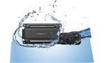
For the amp, I selected the Focal Impulse 4.320 which had the advantage of size, power and convenient wiring location.
![Image]()
Here's the table I made when doing the amp research:
The smallest powered sub I could find is the Pioneer TS-WX010. I actually bought a significantly cheaper gray-market version from Japan on eBay.
![Image]()
For power distribution, I used an Eastern Beaver PC8R relay. This is available directly from Japan. It can supply up to 40 amps to up to 8 fused outputs: 6 switched and 2 unswitched.
![Image]()
I planned to use 4 switched outlets:
![Image]()
This is the USB charger I used. It's basic and in-keeping with the OEM lighter socket and has a nice blue LED backlight.
![Image]()
I installed the amp, the relay and the subwoofer under the dash, using existing holes in the aluminum extrusion at the back of the trinket tray, combined with custom brackets 3D printed in ABS.
The amp half rests on the "shelf" to the left of the driver. It is screwed to a support bracket that is held by two screws to the dash underside and a little clamp to the aluminum extrusion on the side. I also put double-sided adhesive tape where it rests on the aluminum. It is quite secure.
![Image]()
![Image]()
To Be Continued....
Step one was upgrading the speakers. The Kicker CS series are quite shallow. So I designed and 3D printed speaker rings that use the original holes and allowed oversized speakers without cutting away any foam backing or dash material. This is how the Kicker 46CSC654 6-1/2" rears look:
And the Kicker 46CSC54 5-1/4"fronts:
There is no downside to using the rears. However, the fronts sit higher on the dash panel, and getting them installed on the dash in situ is a challenge. I used stainless cap screws as fasteners, and found some useful tricks like grinding down an allen wrench.
For the amp, I selected the Focal Impulse 4.320 which had the advantage of size, power and convenient wiring location.
Here's the table I made when doing the amp research:
| Make | Model | W (in) | H (in) | D (in) | RMS / Chan | AWG | Fuse | Cost | Comment |
| Alpine | KTA-450 | 7.125 | 1.42 | 3.5 | 50 | 12 | 20A | $220 | Wiring connects one end |
| Alpine | KTP-445U Power Pack | 7.44 | 1.5 | 2.5 | 45 | 15A | $290 | Wiring on both ends | |
| Alpine | KTA-30FW Tough Power Pack | 9.2 | 1.75 | 3.75 | 75 | 10 | 30A | $420 | |
| AudioControl | ACM-4.300 | 9.41 | 1.75 | 2.97 | 50 | 8 | 30A | $300 | |
| Clarion | XC2410 | 7.16 | 1.5 | 3.25 | 50 | 40A | $200 | ||
| Focal | FDP Sport V2 | 8.25 | 1.625 | 5 | 150 | 50A | |||
| Focal | Impulse 4.320 | 6.875 | 1.875 | 2.625 | 55 | 10 | 25A | $600 | Wiring connects one end $300 Amazon |
| Focal | FDS 4.350 | 7.75 | 1.5 | 4.25 | 58 | 10 | 30A | $500 | Wiring on both ends |
| Hertz | HMP 4D | 8.78 | 1.72 | 3.96 | 50 | 12 | 15A | $380 | Wiring on both ends |
| Jensen | JA4B | 8.38 | 2.16 | 5.59 | 90 | 25A x 2 | $150 | Wiring on both ends | |
| JL Audio | JD400 | 9.5 | 2.1 | 7.5 | 75 | 8 | 35A | $330 | |
| Kenwood | KAC-M1814 | 5.71 | 1.75 | 3.9 | 45 | 15A | $115 | Not at Crutchfield | |
| Kenwood | KAC-M5014 | 7.81 | 1.94 | 4.125 | 50 | 40A | $249 | ||
| Kenwood | KAC-M3004 | 6.5 | 1.75 | 3.9 | 50 | 10 | 30A | $219 | Wiring on both ends |
| Kicker | 47KEY200.4 | 7.375 | 1.69 | 2.75 | 50 | 12 | 20A | $280 | Wiring on both ends |
| Kicker | 51KPX300.4 | 8.5 | 1.69 | 3.3 | 45 | 8 | 40A | ||
| MTX | MUD100.4 | 8.52 | 1.86 | 5.51 | 50 | 10 | 30A | $270 | |
| Rockford Fosgate | Punch PBR400X4D | 6.8 | 1.5 | 4.3 | 50 | 8 | 60A | $280 | |
| Rockford Fosgate | Power T400X4ad | 7 | 1.6 | 4.3 | 100 | 8 | 60A | ||
| Sony | XMS400D | 6.5 | 1.5 | 2.5 | 45 | 12 | 15A | $150 | Wiring on both ends |
| Sound Ordnance | M75-4 | 7.05 | 1.73 | 4.73 | 75 | 8 | 60A | $160 | |
| Wāvtech | Link300.4 mini | 7.44 | 1.73 | 4.53 | 50 | 8 | 40A | $300 | |
| Wāvtech | Link500.4 mini | 10.2 | 1.73 | 4.53 | 75 | 8 | 60A | $450 |
The smallest powered sub I could find is the Pioneer TS-WX010. I actually bought a significantly cheaper gray-market version from Japan on eBay.
For power distribution, I used an Eastern Beaver PC8R relay. This is available directly from Japan. It can supply up to 40 amps to up to 8 fused outputs: 6 switched and 2 unswitched.
I planned to use 4 switched outlets:
- Amp
- Sub
- USB charger socket (replacing the OEM unswitched ligher socket)
- Radar detector direct wire
This is the USB charger I used. It's basic and in-keeping with the OEM lighter socket and has a nice blue LED backlight.
I installed the amp, the relay and the subwoofer under the dash, using existing holes in the aluminum extrusion at the back of the trinket tray, combined with custom brackets 3D printed in ABS.
The amp half rests on the "shelf" to the left of the driver. It is screwed to a support bracket that is held by two screws to the dash underside and a little clamp to the aluminum extrusion on the side. I also put double-sided adhesive tape where it rests on the aluminum. It is quite secure.
To Be Continued....